

Professional Frame Circuit Breaker Selection and Maintenance Best Practices
2026-10-19
Most frame circuit breaker failures trace back to two root causes: wrong selection at the design stage, and skipped maintenance later. This post compiles best practices from real commissioning and service reports, with insights from Chang Song engineers, to help you choose the right breaker and keep it operational for decades.
Matching Breaker Ratings to Real Fault Currents, Not Just Nameplate Specs
Nameplate specs often paint a static picture, but actual fault current at a breaker's location can shift with transformer impedance, conductor length, and utility changes. Sizing strictly to the label can leave a gap between what the breaker is rated to interrupt and what it might actually face.
Field measurements or a short-circuit study usually reveal lower or occasionally higher values than the nameplate implies. When the calculated available fault current sits below the breaker's interrupting rating, that margin isn't wasted—it often means less arc-flash energy and fewer stress cycles on contacts. The mistake is treating the nameplate rating as the real number instead of an upper limit.
A breaker with a 65 kA rating doesn't need to see 65 kA to do its job; it just needs to clear whatever the system can deliver without coming apart. Matching that real number, rather than the stamped spec, keeps protection honest and avoids overbuilding or, worse, underestimating the hazard.
Why Frame Size Alone Fails: Coordinating Protection Curves Across the Distribution
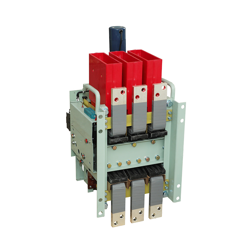
Selecting a circuit breaker by frame size alone ignores the time-current characteristic that determines whether upstream and downstream devices actually coordinate. Two breakers with identical frame ratings can trip in opposite sequences under the same fault because their trip units, instantaneous settings, and published curves diverge. The result is often a localized fault that opens a feeder or main, widening an outage far beyond the faulted branch.
Coordination work has to compare the full protection curves across the distribution, not just ampere ratings. This means plotting the upstream breaker's time-current curve against the downstream device's curve and checking the band between them for overlaps. Where the curves cross or fall inside the same operating band, selective coordination breaks down. The goal is a minimum time margin—commonly 0.1 to 0.3 seconds—between the upstream device's clearing time and the downstream device's total clearing time across all fault currents available at the downstream location.
Ignoring curve coordination also creates hidden risks during motor starting, transformer inrush, or temporary overloads. A frame size that appears conservative can still nuisance trip if its instantaneous pickup sits too low relative to the downstream load profile. Conversely, raising the instantaneous setting to avoid nuisance trips may sacrifice protection against arcing faults. Only by overlaying the actual trip curves, adjusting settings, and testing against the available fault current can a distribution system achieve both selectivity and adequate protection.
Thermal Imaging and Torque Checks: The Overlooked First Line of Defense
Most maintenance teams wait for a loud vibration or an unexpected shutdown before they even think about checking electrical connections. That's backwards. Thermal imaging and torque checks cost almost nothing compared to the damage a single loose lug can cause, yet they're routinely skipped until something fails. A handheld infrared camera can spot a hot spot on a breaker or bus bar weeks before it turns into a meltdown. And a torque wrench takes less than a minute per connection. The trick is making it a habit, not a heroic response.
The value isn't just in catching problems early—it's in understanding how the system ages. Connections loosen over time due to thermal cycling, vibration, and even the settling of conductors. A thermal scan shows you where resistance is building, and a torque check confirms whether the fastener has backed off or the metal has deformed. Together they give you a baseline. Without them, you're guessing. One facility I know started doing quarterly infrared scans on their main switchgear and found three critical hot spots in the first pass alone—all of which would have been invisible to the naked eye and silent to the ear.
Implementing this doesn't require a massive overhaul. Start with the highest-load panels and the oldest equipment. Schedule a walk-through with a thermal camera during peak demand, and mark every connection that reads more than 10°C above ambient. Then follow up with a calibrated torque wrench on those points, plus a random sample of others. Document the readings. Over time, you'll see patterns—certain breakers loosen faster, certain lugs run hot every summer. That data lets you adjust intervals and focus your labor where it matters. It's the cheapest insurance your electrical distribution system will ever have.
Arc Flash Boundaries Change With Breaker Condition—Not Just Settings
When technicians update a breaker's trip settings, they often assume the arc flash boundary shifts in a predictable way. But the hardware itself tells a different story. A breaker that has been racked in and out dozens of times, has worn contacts, or hasn't been exercised in years may not clear a fault at the speed its settings suggest. That delay—even a few cycles—can push the incident energy higher and move the arc flash boundary outward, sometimes beyond the label value.
Mechanical wear, lubrication breakdown, and eroded arc chutes all contribute to slower operation. A breaker that trips slightly late under fault conditions no longer matches the time-current curve used in the study. In the field, this means the calculated boundary is only as good as the breaker's actual condition on the day of the incident. Regular maintenance, contact resistance testing, and exercising the mechanism can help keep the real clearing time in line with the modeled values.
The practical takeaway is that arc flash boundaries are not static numbers engraved on a label. They drift with the health of the protective device. If a breaker has been neglected or heavily cycled, treating the arc flash boundary as unchanged can leave workers unknowingly exposed. Instead, condition data should feed back into the risk assessment, so the boundary reflects the equipment you actually have—not the equipment the study assumed.
Spare Parts Strategies That Prevent Downtime Without Overstocking
Most maintenance teams fight breakdowns by stocking more parts than they’ll likely need, which ties up capital and creates a false sense of security. A sharper approach starts with ranking every part by how long you can afford to wait for it. If a failure stops production immediately, that part justifies a higher stock level; if you have days or weeks of buffer, you can rely on expedited shipping or a nearby distributor instead of keeping it on your shelf. This kind of consequence-based ranking changes the conversation from “what if we run out” to “what actually happens if we do.”
Next, use your own work order history to set realistic min-max levels rather than guessing. Look for parts with frequent but predictable demand, and adjust reorder points based on actual lead times plus a small safety margin. For expensive or rarely used items, consider sharing stock with another facility in your region or setting up a vendor-managed inventory agreement where the supplier monitors usage and replenishes only what’s needed. These arrangements shift the burden of holding slow-moving parts off your balance sheet.
Finally, treat part availability as a design problem, not just a purchasing problem. Standardize components across machines where possible, and build condition-monitoring alerts that give you a heads-up weeks before a part fails. That early warning lets you order replacements in normal shipping windows, so you rarely need deep safety stock. The result is a leaner storeroom that still keeps production moving because every part on the shelf has a clear, current reason to be there.
Documenting Trip Events to Catch Mechanical Wear Before It Cascades
Trip events often get dismissed as nuisance interruptions, but each one leaves a trace. A breaker that trips twice in a week might be fighting a bearing that's slowly grinding itself down. Writing down the exact time, load at the moment of trip, and any unusual noise or vibration turns those interruptions into a timeline. That timeline is where early wear shows up—not as a dramatic failure, but as shorter intervals between events or a slight shift in current draw before the trip.
The value compounds when records are kept without gaps. A single trip note says little; a month of notes can reveal that a motor's startup current has crept upward by a few percent, or that trips cluster after a specific shift change. Those patterns point to mechanical wear long before metal fatigue becomes a broken shaft or a seized gearbox. Catching it at that stage means replacing a $40 bearing during a planned window instead of unwinding a cascade of damaged couplings, misaligned shafts, and unscheduled downtime.
The trick is to make the record effortless enough that it actually happens. A grease-stained notebook near the panel or a quick phone photo of the HMI before resetting works better than a perfect digital form that no one fills out. The goal isn't admin perfection—it's continuity, so the next person sees the same sequence and can spot the trend before it becomes a cascade.
FAQ
Begin with the maximum available short-circuit current at the supply terminals. The breaker's interrupting rating must exceed that value with margin, otherwise you're installing a fire hazard even if the continuous current rating looks right.
Frame size sets the physical and thermal envelope; trip ratings can often be adjusted downward within that frame. Buying a 1600A frame for an 800A load can make sense if future growth is expected, but don't assume every trip unit will fit every frame series.
High enclosure temperatures are the usual culprit. A breaker rated at 40°C will carry less current continuously if the panel interior runs hotter, so you must apply the manufacturer's derating curve—not guess based on room temperature alone.
For a breaker that operates frequently under load, inspect contacts and arc chutes at least annually. Look for uneven erosion, deep pitting, or cracked arc splitter plates. If you see copper splash or heavy discoloration, schedule replacement before the next fault event.
Use dry, oil-free compressed air at low pressure and a soft brush. Never use solvent sprays or WD-40 on arc chambers or insulating parts. After cleaning, manually operate the mechanism a few times and verify contact wipe if the design allows it.
Yes—listen for a change in charging sound, look for slow or jerky closing motion, and check for cracks in the charging handle or chain. If the springs feel weak during manual charging or the breaker takes noticeably longer to close after tripping, stop using it and call for service.
Sometimes, but only within the same manufacturer's approved compatibility matrix. Swapping a trip unit from another brand or a different generation can disable protection functions or cause false trips. Always confirm firmware and sensor compatibility before ordering.
Perform insulation resistance tests phase-to-phase and phase-to-ground, cycle the breaker manually at least five times, verify trip unit settings against the coordination study, and inspect for moisture or rodent damage. If storage was humid, use space heaters or desiccants before applying control voltage.
Conclusion
When selecting frame circuit breakers, relying solely on nameplate specifications can leave a system vulnerable because actual fault currents often differ from calculated values. Matching the breaker's interrupting rating to real-world conditions—not just the label—prevents catastrophic failures during a short circuit. Yet even a correctly sized frame can miscoordinate if protection curves aren't aligned across the distribution network; frame size alone ignores how upstream and downstream breakers interact during faults. A coordinated system requires plotting time-current curves so that the nearest breaker trips first, isolating the fault without disturbing the rest of the facility.
Maintenance practices are just as critical as initial selection. Thermal imaging and routine torque checks on connections catch loose lugs or hot spots before they escalate into insulation breakdown or fires—an overlooked but inexpensive first line of defense. Arc flash boundaries aren't static; they shift as breaker contacts wear and lubrication degrades, so relying on original settings without verifying condition can put workers at risk. Smart spare parts strategies, such as stocking only critical trip units and arc chutes based on failure history, prevent downtime without overflowing the storeroom. Finally, documenting every trip event—not just the fact that it tripped, but the current, duration, and mechanical sounds—reveals early signs of wear like sluggish linkages or pitted contacts, allowing intervention before a cascade failure. These habits, woven into daily routines, keep frame breakers reliable far beyond their nameplate ratings.
Contact Us
Contact Person: Tonglun Chen
Email: [email protected]
Tel/WhatsApp: 8618906642555
Website: https://www.cncsele.com